Menu
FLV Non-Metallic Bag Filter Sizing using Calculated Clean Differential pressure.
FLV Bag filters are typically sized so that there is a 2 to 3 psi or less pressure loss across them with a clean bag installed. (3 psi = 20.6 kPa)
Flow and Velocity Limitations – Hayward FLV Bag Filter - The Hayward FLV Bag Filter housing has two key operating limitations that must be observed:
Connection Velocity Limitation
- The maximum allowable fluid velocity through the filter housing connections is 8 feet per second.
- This velocity limit applies regardless of the filter bag size installed.
Bag Size Flow Limitations
- Size 01 filter bag: Maximum recommended flow rate is 100 US gpm, irrespective of connection size. (100 US gpm = 22,712 lt/h)
- Size 02 filter bag: Maximum recommended flow rate is 150 US gpm, irrespective of connection size. (150 US gpm = 34,068 lt/h)
In summary, both the 8 ft/s connection velocity and the bag size maximum flow rating must be respected. The lower of these two limitations will determine the actual maximum flow capacity for your installation.
The following charts apply only to Standard Nominal Rated Felt and NMO filter bags. For applications requiring High Removal Efficiency filter media, please contact our sales team for guidance.
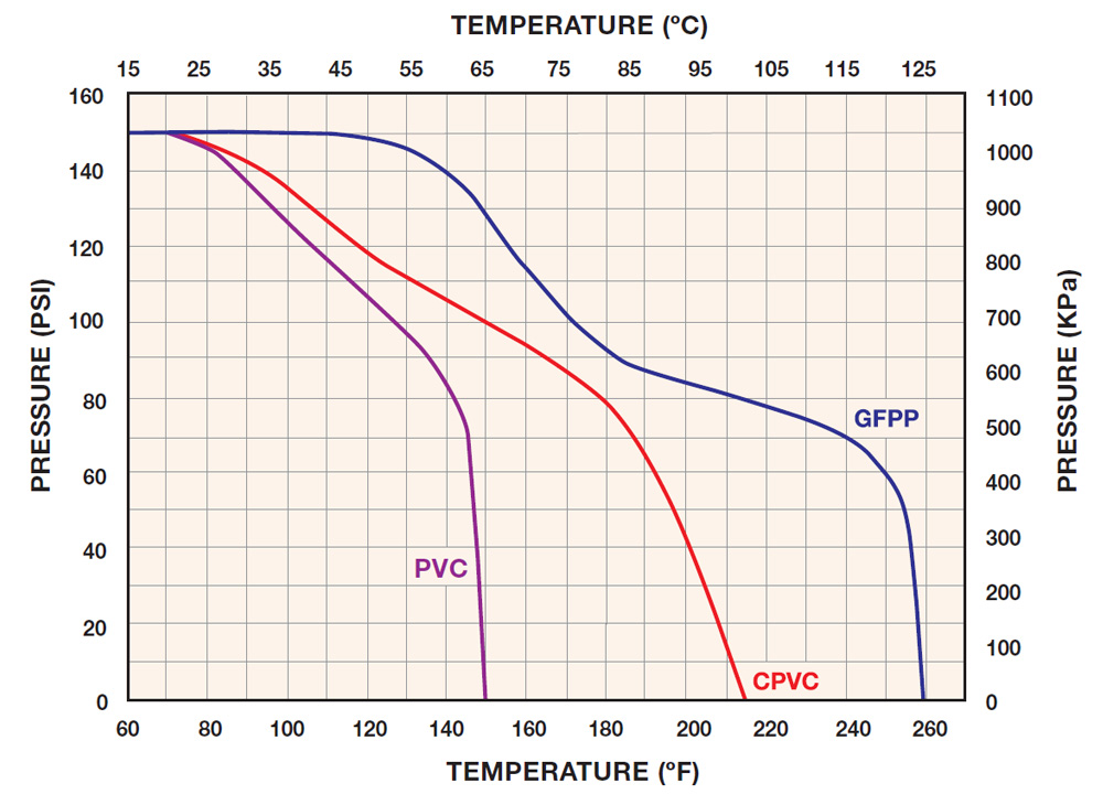
CHECK THE TEMPERATURE AND PRESSURE RATING OF THE MATERIAL OF CONSTRUCTION
To make sure that the temperature/pressure of the application falls within the OK range, see the chart on each individual catalog page or check the chart above for FLV Series Filters.
DETERMINE THE FLOW RATE
In GPM, of the system into which the bag filter is to be installed. Hayward® single and double length bag filters work with flows of up to 150 GPM. If the system’s flow rate is greater, consider using two or more filters manifolded together in parallel. For example, if the system flow rate is 150 GPM or higher, using two manifolded filters would reduce the flow to a manageable 75 GPM through each. Constantly running the flow through the filters at their maximum rating limit is not recommended.
SELECT THE BAG
Hayward bags are available from 1 to 800 microns. The bags are made from several types of materials and are either of a sewn or welded construction. All bags are sold in Carton Quantities. A single length bag (01 Size) has a surface area of 2.0 sq ft and a double length (02 Size) of 4.1 sq ft. Please note: the below charts provide pressure loss per square foot.
CONSIDER START-UP PRESSURE LOSS
Bag filters are typically sized so that there is a 2 to 3 PSI or less pressure loss across them with a clean bag installed. Keep in mind that this is just a guide. The time between bag change-outs for a double length filter is more than twice that of a single length filter in the same application.
CALCULATE START-UP PRESSURE LOSS
To figure the total pressure loss across the filter with a clean bag requires making two pressure loss calculations and adding them together: The loss across the filter without a bag and the bag loss.
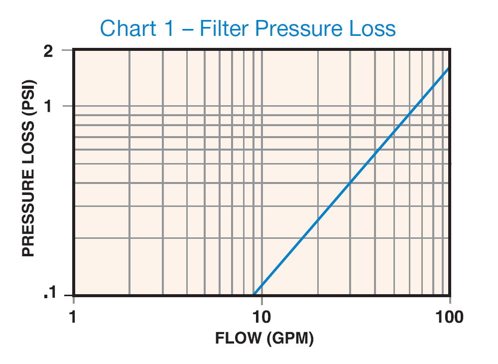
Step 1 - Determine pressure loss across housing only
Use the system flow rate and Chart 1 to determine the loss across the filter without a bag (01 single and 02 double length filters have virtually the same pressure loss without a bag).
Example: A flow rate of 30 GPM results in a 0.4 PSI pressure loss. If the process media is water or has a viscosity less than 200 CPS, that’s it. If the viscosity is greater, select the correction factor that matches the process media viscosity in CPS units from Table Number 1. Multiply the pressure drop by this factor.
Table 1 – Filter Viscosity Correction
| VISCOSITY IN CPS | 200 | 400 | 600 | 800 |
|---|---|---|---|---|
| CORRECTION FACTOR | 1.10 | 1.20 | 1.40 | 1.50 |
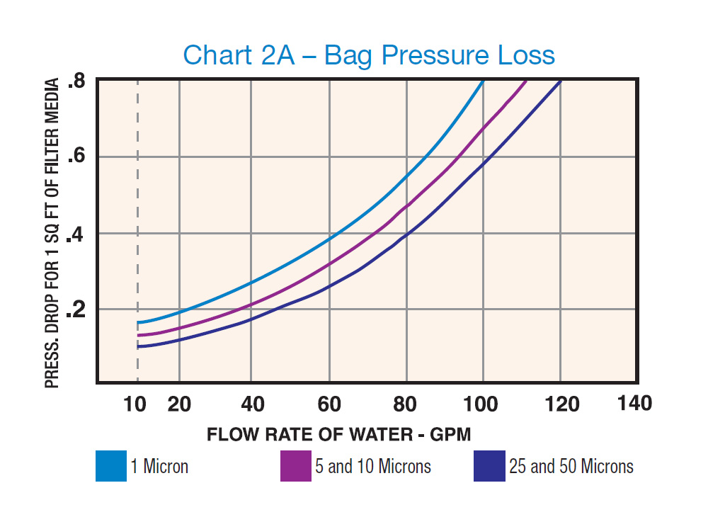
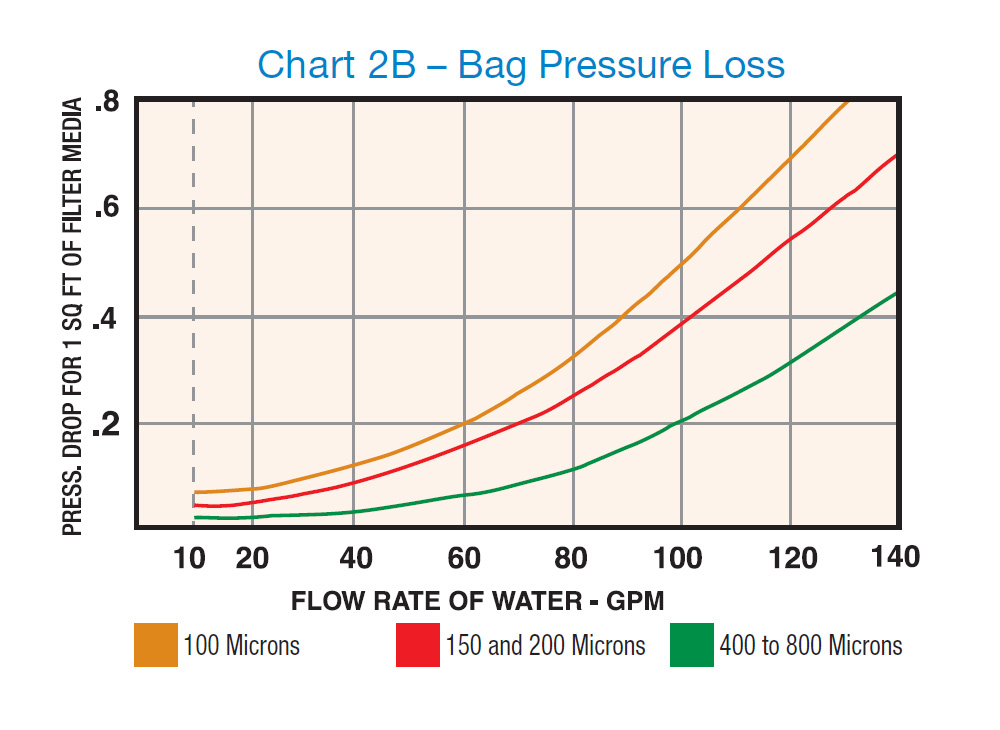
Step 2 - Determine pressure loss across bag only
Single (01 size) and double (02 size) length filter bags have different pressure losses. Use Charts 2A and 2B to determine the pressure loss per square foot of bag surface.
Example: with a system flow rate of 30 GPM, a 5 or 10 micron bag would have a 0.2 PSI loss per square foot. This loss is divided by 2.0 (surface area of 2.0 sq ft) for a single (01) length bag or 4.1 (surface area of 4.1 sq ft) for a double (02) length bag. These factors are the respective surface areas of the bags in square feet.
The loss for a single bag would be 0.1 PSI (0.2 ÷ 2.0) and 0.05 for a double length bag (0.2 ÷ 4.1).
For fluids with viscosities other than water, select the correction factor from Table 2 and multiply the pressure drop by it. Example: If the fluid viscosity were 800 CPS, the pressure loss for a single length bag would be 5.0 (0.1 x 50.0).
Table 2 – Bag Viscosity Correction (Water = 1 CPS)
| VISCOSITY IN CPS | 1 | 50 | 100 | 200 | 400 | 600 | 800 |
|---|---|---|---|---|---|---|---|
| CORRECTION FACTOR | 1.00 | 4.50 | 8.50 | 16.60 | 27.70 | 38.90 | 50.00 |
Chemical Resistance
Please note: It is the ultimate responsibility of the end user to determine the compatibility of the chemical being used in his or her particular application.
Always refer to the products Installation, Operation and Maintenance Instructions (I.O.M.)
Step 3
Add the pressure loss of the filter (from step 1) and the filter bag (from step 1) together to get the total estimated clean pressure loss across the filter with the bag installed.
Example - 30 GPM US (6,814 lt/hour) @ 1 CP (Water)
| 01 Size | 02 Size | |
| Vessel Loss 30 GPM US | 0.4 | 0.4 |
| 5 Micron Bag Loss 30 GPM US @ 1 c.p. | 0.1 | 0.05 |
| Total DP in PSI | 0.5 | 0.45 |
| Total DP kPa | 3.44 | 3.10 |
Example - 30 GPM US (6,814 lt/hour) @ 200 CP
| 01 Size | 02 Size | |
| Vessel Loss 30 GPM US @ 200 c.p. | 0.44 | 0.44 |
| 5 Micron Bag Loss 30 GPM US @ 200 c.p. | 1.66 | 0.83 |
| Total DP in PSI | 2.1 | 1.27 |
| Total DP kPa | 14.47 | 8.75 |
Monarch Asia Pacific Pty Ltd
Trading as Monarch Industrial Products
ABN 60 141 555 688
Unit 3, 8 Bult Drive, Brendale, QLD 4500
AUSTRALIA
Phone: +61 (0) 7 3889 9949
![]()


Monarch Asia Pacific Pty Ltd, © 2026 All Rights Reserved
Release: 26:6:0